|
|
Post by hal on May 1, 2022 12:47:45 GMT 1
One for Robert Arthur or Le Dolly or an electrician (are there any more here?) please. See photo of a mechanical timer clock below. A questions please - what does the 16 (8) A on the back of the clock mean? Is it saying that the n/o contact is 16 or 8 Amps or what? I have never seen this described as such before. Help appreciated!  Attachments: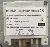
|
|
|
|
Post by pcpa on May 1, 2022 14:05:04 GMT 1
I propose ditching the contractor and wiring 1 and 2 to a 16A MCB bridging 1 to 3 and 2 to 4 then running 3 to the + of the pump and 4 to the Neg of the pump... That will create an interesting result when the contact changes over! At least you will get to test the 16 amp disjoncteur. In view of your above scheme I am reluctant to tell you how it should be done in case you misinterpret it and it's rare that I say it but I think you should get a qualified electrician in to do the work. Suffice to say that you should really use a contactor with the correct rating for the pump (which you dont specify), if you choose to rely on the relay contact in the timer you should retain the 2amp disjoncteur for the motor and feed the relay common contact from a seperate correctly rated one. In my experience the contacts on timers rarely live up to the claimed rated current, if yours are to be believed then the nomenclature is probably 16 amp resistive load, 8 amp inductive load. I would only use it for driving the coil of a contactor. |
|
|
|
Post by hal on May 1, 2022 14:27:31 GMT 1
Thanks papa - I have changed the wording of my post.
I never learn that on a forum, only ask the question and not quantify why I am asking it! But thanks for your suggestion.
|
|
|
|
Post by pcpa on May 1, 2022 14:36:20 GMT 1
For someone who has just been saved from creating a dead short between live and neutral on a 16 amp disjoncteur you are less than magnanimous in your appreciation. I also answered your question that remains.
Or maybe you havn't been saved because your strange attitude towards me (considering what I have done for you in the past) has prevented you from understanding the danger that your scheme of "bridging 1 to 3 and 2 to 4" would create, when the contact changes over and links contacts 3 and 4 you create a dead short between live and neutral fed from the 16 amp MCB
|
|
|
|
Post by hal on May 1, 2022 14:50:01 GMT 1
Yes, I transcribed my numbers I wanted to bridge incorrectly. I realised this over lunch and dashed back hoping the post was not opened.
As I say, I should only ask the question I wanted answering and not opened up anything for discussion!
You did not 'save' me from anything, rather you patronisingly said it would be an interesting result. That is not saving!
|
|
|
|
Post by hal on May 1, 2022 16:03:08 GMT 1
Mr Google found me some answers! This 16 (8) A is a switch rating that allows 16A ac but only 8A dc...correct?
Where then does the mu (I cannot find how to type a mu on the keyboard) come in? I thought mu means 'micro'...no?
|
|
|
|
Post by robertarthur on May 1, 2022 16:19:01 GMT 1
@ Hal, I had a look at the specifications of your timer: it's 16 amps for a resistive load and 8 amps for an inductive load (an electrical motor). Incandescent lamp load: a maximum of 1300 W. |
|
|
|
Post by hal on May 1, 2022 16:24:19 GMT 1
So the various items I see on google are wrong? Or are DC loads classed inductive? And why the 'mu'?
As it happens, 8A is good as the pump is 5.
|
|
|
|
Post by hal on May 1, 2022 16:27:50 GMT 1
And on the subject of inquisitiveness, what would happen if on this switch say, a motor higher than 8A was wired in?
|
|
|
|
Post by robertarthur on May 1, 2022 16:54:05 GMT 1
@ Hal, equipment with coils is inductive, your motor as an example. Electrical motors have nasty habits: very high inrush currents when starting. So eventually the switch contacts will burn out when overdoing it with too heavy loads. And will also produce sparks when shutting down. Every spark takes away a bit of the metal surface of the switch contacts, so contact resistance increases and the switch will warm up. This process of slow self destruction will gradually pick up speed: the end of a nice timer.......
|
|
|
|
Post by pcpa on May 2, 2022 0:16:32 GMT 1
It so amuses me when Hal ignores (or worse) my answers to his electrical questions but when someone else gives exactly the same information shortly afterwards he is all ears and appreciative.
|
|
|
|
Post by hal on May 2, 2022 8:04:26 GMT 1
I am not all ears as you say nor appreciative- in fact only one of my questions has been answered! I still do not know why there is the mu symbol on the item schematic and I do not know what would happen if I put an inductive load higher than spec'd on a switch. Answer these and I will be appreciative.
But when you do reply to something that is obviously wrong - by mistake or ignorance, with patronising garbage like you did, no, I do not go beyond the first sentance. Would you?
I blame myself though for giving unnecessary detail, so do not get over amused.
|
|
ibis
Banned Member
Posts: 1,376
|
Post by ibis on May 2, 2022 8:13:15 GMT 1
Just get a professional..
|
|
michael86
Member
Vienne 86 and England
Posts: 65
|
Post by michael86 on May 2, 2022 10:13:45 GMT 1
Hi Hal. The schematic picture at the bottom of the label is marked with a capital M in a circle for the motor and a mu symbol for the microswitch. The legend above the picture shows the capital M in a circle, the motor, is 230v 50 Hz and the mu symbol, the microswitch, is 16(8)A at 250v.
As Robert said, if you overload the switch it will burn out more quickly.
Michael
|
|
|
|
Post by hal on May 2, 2022 10:35:40 GMT 1
O Kaay - I get it now! 'mu - switch'. makes sense I guess if you know what you are talking about!
Thanks all !
|
|


